Concept of measurement
Measurement is a word used in everyday life. We measure a piece of land in hectares or acres, and the circumference of a playground using a tape measure. In physics, accurate and precise measurements enable the collection of useful experimental data that can be tested against theoretical predictions to enhance the development of physical theories.
In this lesson, you will learn the concept of measurement of physical quantities, the basic apparatus/equipment used in measurement and how to use them. The competencies developed will enable you to deal with measurements in different context.
Concept of measurement
The word ‘measurement’ comes from the Greek word ‘metron’ which means ‘limited proportion’. It is our common experience that, if you want to buy a trouser, the information that a shopkeeper first wants to know is the size of the trouser that fits your waist. If you do not know your size, he or she will take a tape and measure the size of your waist. The act of finding the size of a given quantity is referred to as measurement.
Measurement involves the process of assigning a numerical value and a unit to an observation or event. It is done by comparing the known and unknown quantities. For example, when you want to determine the length of a table, you use a ruler or a tape measure, which has predefined units, to compare with the table. The number of units that match the length of the table becomes the numerical value representing the length of the table.
Every measurement has two parts which are:
1. A number or numerical part that gives the result of the comparison; and
2. A unit part which identifies the particular unit used to make the measurement.
In the unit part, the focus is on the standard unit (Systeme Internationale or International System Units-SI units) though, other units may also be used. For example, if the length of a playground is 100 m, ‘100’ is the number part while ‘m’ is the unit part. Therefore, a meaningful measurement must have both a number and a unit.
A complete measurement that includes both number and unit parts is called a measurement of a physical quantity. For example, the measurement of 100 km, 2 kg or 10 s.

Physical quantity
A physical quantity is any measurable quantity. Physical quantities are divided into two categories, namely fundamental physical quantities and derived physical quantities.
Fundamental physical quantities
Fundamental physical quantities are quantities of measurement which cannot be expressed in terms of other quantities. These include; length, mass, time, temperature, amount of substance, electric current, and luminous intensity.
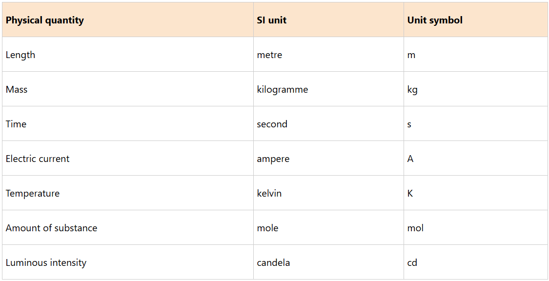
Among the measured fundamental physical quantities mass, length and time are the most common. Table below shows the fundamental physical quantities and their respective SI units.
Fundamental physical quantities and their SI units
Vector and scalar quantities
The physical quantities can further be classified into either vector or scalar quantities.
Vector quantities
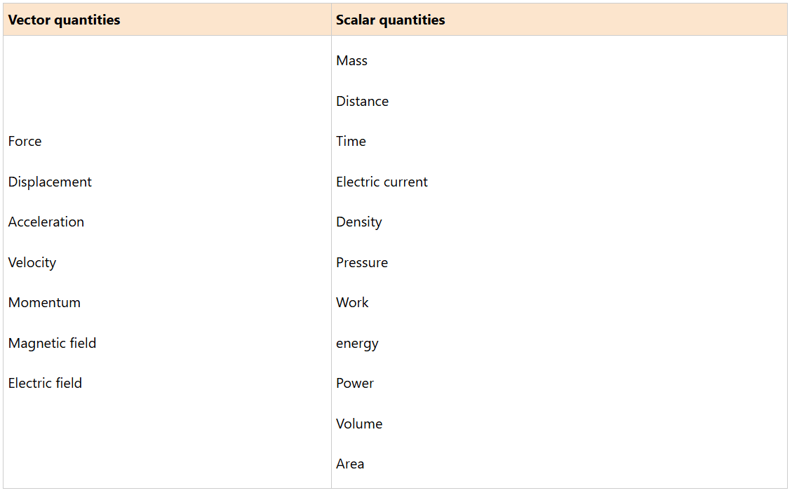
Vector quantities are those quantities that have both magnitude and direction. Examples of vector quantities are force, displacement, velocity, and momentum.
Scalar quantities
Scalar quantities are those quantities that have magnitude but have no direction. Examples of scalar quantities are mass, distance, time, density, volume, pressure, speed, electric current, work, energy, and power.
For example, consider a car traveling at a speed of 100 kilometres per hour North. This describes the velocity of the car which is 100 kilometres per hour in the North direction.
Velocity is a vector quantity. However, if the intention is to describe only the speed of the car and not the direction, the statement could be simply that the car is travelling at 100 kilometre per hour. Speed is a scalar quantity. Table below gives some of the vector and scalar quantities.
Measurement of Length
Length is the most commonly measured quantity in daily life. Length is used to give the dimensions of an object or the distance between two points. Hence, distance is defined as the path taken by a particle in space between two points or objects.
The distance around the surface of an object is called the perimeter. You can measure the distance ranging from small to large distances such as the distance from the earth to the sun.
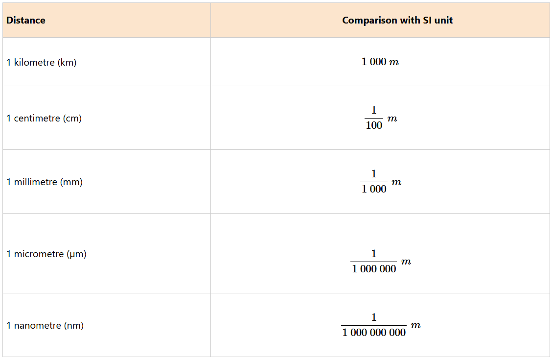
To cope with these differences, there are several other units obtained from the metre, namely, kilometre (km), centimetre (cm), millimetre (mm), micrometre (μm), nanometre (nm), picometre (pm) and femtometre (fm).
Their equivalence is as follows:
1 km = 1000 m;
1 m = 100 cm;
1 cm = 10 mm;
1 mm = 1000 μm;
1 μm = 1000 nm;
1 nm = 1000 pm;
1 pm = 1000 fm.

The length of an object is measured using specific instruments. The choice of an instrument to be used is determined by the following factors:
1. The desired degree of precision.
2. The size of the physical quantity to be measured.
3. The shape of the object.
Gives some of the units in comparison to the metre
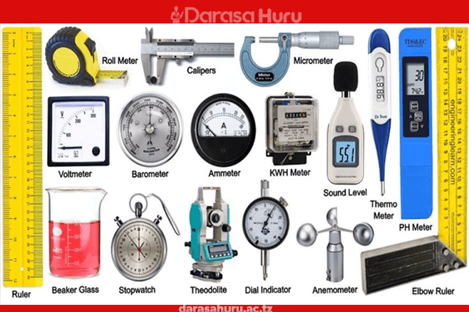
Basic equipment/apparatus and their uses
The basic equipment or apparatus for measurements in physics serves as an essential foundation for conducting experiments and obtaining reliable data. This equipment includes measuring instruments such as rulers, callipers, and micrometres, which provide accurate length measurements, as well as balances to quantify mass.
These tools enable physicists to explore fundamental principles, ensure precision in their measurements, and contribute significantly to the advancement of scientific knowledge.
Ruler
A ruler is a measuring instrument used to determine the length or distance of objects. It typically consists of a flat, rigid strip marked with units of measurement, enabling users to obtain precise measurements easily.
Classification of ruler
The rulers have been classified into two categories such as rigid rulers and the flexible rulers. Each category of ruler serves its purpose according to the length of measurement required, with varying levels of portability and application suitability.
Rigid Rules
Rigid rulers are solid and do not bend, providing consistent accuracy in measuring straight lines. Common types include metre ruler, 50 cm ruler and 30 cm ruler as discussed hereunder.
Metre Rule: This rule has a length of 1 metre (100 centimetres). It is commonly made of wood, plastic, or metal and is primarily used for measuring longer distances, often in educational and professional settings like classrooms and workshops. Suitable for measuring larger objects and distances, making it ideal for geometry, craft projects, and mechanical work.
A 50 cm Rule: It is sometimes referred to half metre rule because it has a length of 50 centimetres (0.5 meters). A 50 cm ruler is more compact than a metre ruler, often favoured for portability and ease of use in smaller projects. Commonly used in schools for drawing straight lines, measuring paper, and conducting small experiments. It is also popular among artists and designers.
A 30 cm Rule: A 30 cm ruler is typically the smallest of the three categories and is often made from flexible materials or plastic. Ideal for students, it is commonly used for everyday tasks like measuring small items, drawing straight edges, and creating precise lines in artwork or homework assignments.
(a) 50 cm rule
(b) 30 cm rule

Flexible Ruler
Flexible rulers can bend and curve, making them suitable for measuring lengths that are not straight.

Tape Measure:
This kind of flexible ruler typically extends anywhere from 1 metre to 10 meters or more. It consists of a long, flexible strip marked with measurements, often housed in a retractable case.
It can easily bend around curves or objects and latch onto edges for precise measurements. Such a ruler is widely used in construction, tailoring, and DIY projects, it is also ideal for measuring curved surfaces, large distances, and irregular shapes where rigid rules might be ineffective.

Task 1
1. If asked to measure the length of a field, which type of instrument will you use? Why?
2. Place the following objects on the paper a pencil, a book and a matchstick. Mark the end points of each. Draw the line-segment connecting the points. Find the length of each object by measuring the distance between the points.
When taking a measurement, always ensure that your eye is perpendicular to the mark on the scale of the metre rule, as demonstrated in Figure 2.3, otherwise the value will have an error.
An error caused by wrong positioning of the eye is known as parallax error. Such an error occurs when the measurement of the length of an object is more or less than the true length, because of the eye being positioned at an angle to the measurement mark

Care should be taken while using a metre rule so as to avoid damaging the ends. This is because the rule does not have an allowance (a short ungraduated portion) for wear at both ends. Suppose, you wish to measure the length of a table. The zero (0 cm) mark of the metre rule is aligned with one end of the table, as shown in Figure below

Since the metre rule does not extend beyond the end of the table, carefully mark the point on the table that corresponds to the end of the metre and then continue, as shown in Figure below

The actual length of the table is then given as: 100 cm + 40 cm = 140 cm. Therefore, the table has a length of 140 cm or 1.4 m.
In case the edge of a ruler is worn out, which is almost inevitable and the zero (0 cm) mark not clearly seen, it is advised to:
(i) always start measuring from the mark more than zero; and
(ii) subtract the mark from the final reading.
Figure 2.6 illustrates the use of a ruler with worn-out edges.

The length of the object is, 9.6 cm – 3.2 cm = 6.4 cm.
Task 2
Measure the length and width of the cover of your physics textbook to the nearest tenth of a centimetre. Record your results. Calculate the perimetre of the cover.
Perimetre = 2 times the length + 2 times the width = 2 (l + w)
Activity 1
Aim: To measure lengths of different objects.
Materials: metre ruler, tape measure, paper and pen
Procedure:
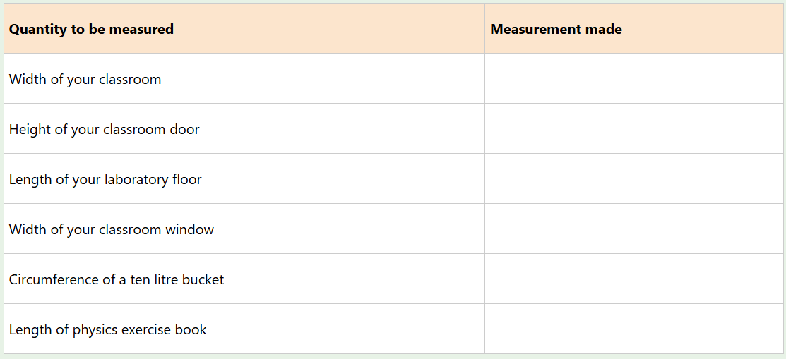
1. Walk around your school compound, identify the objects presented in Table below.
2. Measure the lengths the objects provided and record in Table below
Questions
1. Imagine your Physics teacher asks you to measure the length of a playing ground. Which type of instrument will you use? Why?
2. How can you apply the skills learnt in this activity in your daily life activities?
Callipers
Callipers are precision measuring instruments characterized by two adjustable arms or jaws designed to measure the dimensions of an object, such as its length, width, thickness, or diameter.
The device can come in several types, including vernier, and digital callipers, each offering different methods for reading measurements, such as ruled scales or electronic displays.
The accuracy of measurements taken with callipers depends significantly on the skills of the user and the proper application of the tool against the object being measured.
Vernier calliper
A vernier calliper is an instrument used to measure small lengths with a greater degree of accuracy than a metre rule. It is used to measure objects to the nearest hundredth of a centimetre, which means its accuracy is 0.01 cm.
A vernier calliper has a fixed scale and a vernier scale. The fixed scale is also known as the main scale. The vernier scale slides along the fixed scale hence readings are taken from both scales. The fixed scale gives readings in centimetres and millimetres.
The vernier scale gives readings in the hundredth of a centimetre. That is, the vernier scale gives the second decimal place of the measured value. Figure 2.7 shows parts of a vernier calliper.

Digital calliper
As with the normal vernier calliper, the digital callipers also consist of mechanical parts like external jaws, internal jaws, stem, and screw lock and we cannot find the main scale, vernier scale because this is a digital vernier so there will be no use and necessity of main scale and vernier scale; instead, we can see the reference scale on the digital vernier calliper.
This kind of calliper is automatic, so it certainly uses electrical and electronic parts for its working, therefore, the components that respond to the digital system are capacitance Sensors, LCD, copper plates, chips, and battery as shown in Figure below

The vernier scale is shorter scale than the main scale. 10 vernier divisions cover 9 main scale divisions. This is a length of 0.9 cm. When this is divided into 10 equal intervals, the result is the difference between the main scale division and the vernier scale division. This is known as Least Count.
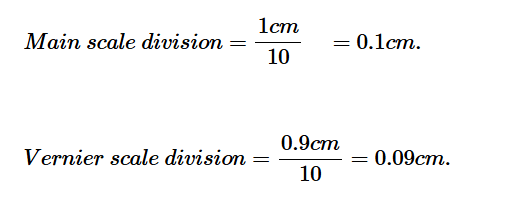
Therefore,
least count of a vernier calliper = (0.1 – 0.09) cm = 0.01 cm.
The vernier calliper has a set of jaws that can be used to measure the length thickness, and depth of objects as shown in Figure below

At the top of a vernier calliper are two inner (upper) jaws that can be used to measure the internal diametre of a hollow object, shown in Figure below. A stem that sticks out from the right side of the calliper is called a depth gauge or the depth probe.
It can be adjusted to measure a depth of an object, as shown in Figure 2.11. The screw clamp visible on top of the calliper is tightened to secure the objects being measured so that the reading does not change while measuring.

Measuring the inner diameter using inside jaws

Measuring depth using the vernier calliper
How to read a vernier calliper
The following steps are taken when measuring length using a vernier calliper.
1. Close the jaws of the vernier calliper and look out for the zero mark (0 cm) differences.
2. Place the object to be measured between the jaws.
3. Slide the vernier along the main scale until it just touches the end of the object.
Use the screw clamp to secure the object in position, shown in Figure below

Measuring the diametre of a steel ball bearing
4. Read and record the reading on the main scale which is to the left of the zero cm mark of the vernier scale. This value is to the nearest tenth of a centimetre.
5. Observe along the vernier scale and record the mark which coincides with a mark on the main scale.
6. Read and note down the value on the vernier scale. This gives the digit in the hundredth place of the measurement.
7. Add the values in steps 4 and 6 to get your correct reading. Therefore, the length of the object = main scale reading + vernier scale reading.
Example 1
Using Figure 2.13, determine the diametre of the object that is placed between the jaws of the vernier calliper.

Solution
From Figure 2.13,
Main scale reading = 3.1 cm
Vernier scale reading = 2 divisions × 0.01 cm = 0.02 cm
Total reading
= Main scale reading + Vernier scale reading
= 3.1 cm + 0.02 cm
= 3.12 cm
The total reading = 3.12 cm
Therefore, the diametre of the object = 3.12 cm.
Example 2
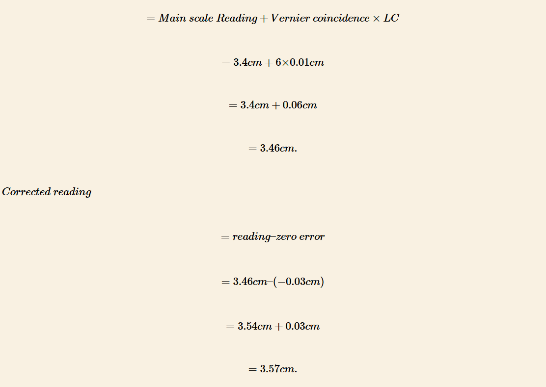
The jaws of the vernier calliper make contact with the inner wall of the calorimetre without exerting any pressure and the zero scale of the vernier reading on the main scale as 3.4 cm, the 6th vernier scale division coinciding with a main scale division, and a vernier constant of 0.01 cm.

(a) How might the presence of a negative zero error in the vernier scale of the calliper impact the determination of the actual internal diametre of the calorimeter?
(b) Calculate the precise internal diametre of the calorimetre when we notice that the vernier scale has a negative zero error of -0.03 cm.
Solution
(a) To calculate the actual internal diametre of the calorimetre while accounting for the negative zero error in the vernier scale.
(b) Main scale reading = 3.4 cm
Least count (L.C) = 0.01 cm
Vernier coincidence = 6
Reading
Exercise 1
1. Draw both the main and vernier scales of a vernier calliper to show a reading of 0.36 cm.
2. What is the reading shown in Figure below?

3. (a) What is the significance of the design of the vernier calliper and its readings when measuring the depth of the beaker, and how does the alignment of vernier scale divisions with the main scale affect the accuracy of the measurement?
(b) In a scenario where a thin metallic strip on a vernier calliper descends from the upper edge to the lower edge and makes contact with the surface of a beaker, the main scale displays a reading of 6.4 cm, with a vernier constant of 0.1 mm, and the 4th vernier scale division aligns precisely with a main scale division. Determine the precise depth of the beaker, assuming there is no zero end error.
Activity 2
Aim: To measure the external diametre of a test tube using a vernier calliper.
Materials: Test tube and vernier calliper
Procedure
1. Close the jaws of the vernier calliper and observe the zero cm mark of the main and vernier scales. Record your observations.
2. Open the jaws and place the test tube between them.
3. Close the jaws gently until the test tube is held firmly. Record your observations.
4. Repeat steps 1 to 3 using other parts along the test tube.
5. Obtain three readings. Record your observations.
Questions
(a) Calculate the average of the readings obtained.
(b) Were the four obtained readings equal?
(c) Why was it important to take four readings and not one?

A test tube is cylindrical in shape. This means that its diametre is the same throughout. The readings obtained using the outside calliper jaws are equal in magnitude since the test tube is almost uniform in shape.
In an experiment, it is always best to obtain many readings so as to obtain an average result. Two or more readings offer an opportunity for the experimenter to compare and identify any pattern.
Task 3
Collect a variety of objects such as books, pencils, beakers, test tubes and other materials available at your physics laboratory. Use a vernier calliper to measure the thicknesses of the collected objects. The depth, internal and external diameters of the hollow objects should also be measured. Record your measurements in the following table:
|
Object |
Dimension (cm) |
Main scale reading (cm) |
Vernier scale reading (cm) |
Actual reading (cm) |
A micrometre screw gauge
Vernier scale reading (cm) Actual reading (cm) A micrometre screw gauge gives readings with better precision than the vernier calliper. Measurement can be obtained to the nearest thousandth of a centimetre.
This is an accuracy of 0.001 cm. For this reason, it is usually used to measure the diameters of thin objects like wires and ball bearings. The micrometre screw gauge has different parts, as shown in Figure below

A micrometre screw gauge consists of main scale (sleeve) and thimble scale. The main scale is marked in millimetres. The thimble scale is divided depending on the distance between two consecutive threads of the screw.
This is called the pitch of the screw. If the pitch of the screw of the micrometre is 0.5 mm, then the thimble scale has 50 equal divisions. Otherwise, it has 100 divisions when the pitch is 1.0 mm.
This means that when the thimble makes a complete turn, the spindle moves either forward or backward a distance of 0.5 mm or 1.0 mm respectively along the sleeve. When the spindle is completely closed onto the anvil, the thimble edge aligns with the zero mark on the sleeve scale.
The thimble also has its zero-mark lying on the central line of the sleeve scale. Therefore, the gap between the spindle and the anvil equals the distance between the edge of the thimble and the zero mark on the main scale.
Measuring the diametre of a wire by micrometre screw gauge
The following are procedures for measuring the diametre of a wire using micrometre screw gauge.
1. Unscrew the thimble to create enough space to accommodate the wire between the spindle and the anvil.
2. Close the gap by rotating the thimble clockwise. Screw the ratchet knob until it clicks so as to show the correct setting.
3. Read and note down the value on the sleeve; that is the last mark must be visible to the left of the thimble. This value is to the nearest tenth of a millimetre. For example, in Figure 2.16, the value is 7.5 mm.

4. Read and note down the value on the thimble that is just below the reference line on the sleeve. This value is to the nearest hundredth of a millimetre (0.28 mm for Figure 2.16).
5. Add the values in steps 3 and 4.
Therefore, for Figure 2.16,
Reading = Sleeve Scale Reading (SSR) + Thimble Scale Reading (TSR)
= SSR + TSR
= 7.50 mm + 0.28 mm
= 7.78 mm
Task 4
Diametre of a steel ball is measured using a vernier calliper which has divisions of 0.1cm on its main scale (MS) and 10 divisions of its vernier scale (VS) match 9 divisions on the main scale. Three such measurements for a ball are given in the following table.
Example 3
What is the correct reading for the micrometre screw gauges shown in Figure 2.17?

Solution
From Figure 2.17 (a)
Main scale reading = 7.50 mm
Thimble scale reading = 0.38 mm
Reading = 7.88 mm.
From Figure 2.17 (b)
Main scale reading = 7.50 mm
Thimble scale reading = 0.22 mm
Reading = 7.72 mm.
Example 4
(a) Explain how the components of the screw gauge, including the sleeve and thimble readings, as well as the least count, are utilized to determine the precise diametre of the rod. What factors should be considered to ensure the accuracy of this measurement?
(b) In the process of measuring the diametre of a rod using a micrometre screw gauge with a least count of 0.01 mm, the sleeve shows a reading of 1.6 cm, and the thimble indicates 48 divisions. Calculate the accurate diametre of the rod.

Solution
(a) To calculate the accurate diametre of the rod using the screw gauge, we need to consider the contributions of both the sleeve and the thimble, taking into account the least count of the instrument.
(b) Least count (LC) of a micrometre screw gauge given = 0.01 mm.
Main scale reading (MSR) = 1.6 cm or 16 mm.
Circular scale reading (CSR) = 48 divisions.
The reading = MSR + CSR × LC
= 16 mm + 48 × 0.01 mm
= 16.48 mm
The correct reading
= 16.48 mm + 0.03 mm
= 16.51 mm.
Exercise 2
1. What is the reading of the micrometre screw gauge in Figure belo?

2. What is the difference between a micrometre having 100 divisions and one with 50 divisions?
3. Write limitations of using a micrometre screw gauge to measure length.
4. The actual diametre of a lead ball is 3.21 mm. Determine the reading that would have been obtained if:
(a) a micrometre screw gauge was used.
(b) a vernier calliper was used.
5. When a screw gauge with a least count of 0.01 mm is used to measure the diametre of a wire, the reading on the sleeve is found to be 0.5 mm and the reading on the thimble is found to be 27 divisions. What is the correct diametre of the wire, if the zero error for the gauge is -0.005 cm ?
Activity 3
Aim: To measure the diametre of a steel ball using a micrometre screw gauge.
Materials: Micrometre screw gauge and steel ball
Procedure
1. Unscrew the thimble to create a gap between the anvil and the spindle.
2. Hold the steel ball in the gap while rotating the thimble clockwise until it gently grips the ball.
3. Keep rotating the ratchet knob until it clicks.
4. Record your observations.
5. Unscrew the thimble slightly. Free the ball and turn it through a certain angle. Then repeat step 3 and 4.
6. Repeat step 5 for different rotation angle.
7. Re-measure the diametre of the steel ball using the vernier calliper and record your readings.
Questions
(a) Calculate the average of the obtained readings.
(b) Why would you prefer a micrometre screw gauge over a vernier calliper when measuring the diametre of a steel ball?

A micrometre screw gauge is more accurate than a vernier calliper. It measures up to three decimal places in the unit of mm. This means that its degree of accuracy is to the nearest thousandth of a centimetre. Unlike a micrometre screw gauge, a vernier calliper can only measure to a hundredth of a centimetre.
Task 5
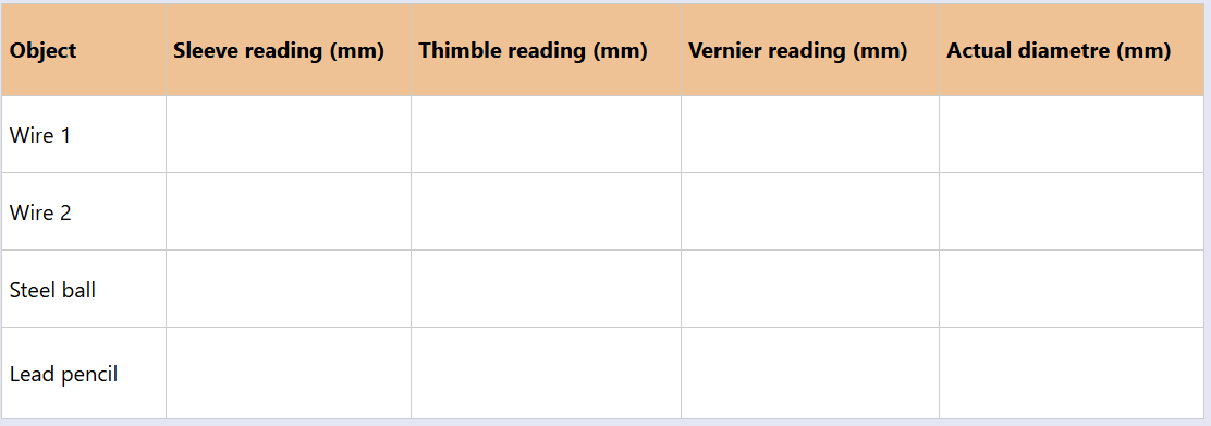
Collect variety a of wires of different diameters, lead pencils and steel balls.
1. Find out the smallest division on the main scale of your micrometre screw gauge and the number of divisions on the thimble.
2. Measure the diameters of the different objects. Record your findings in the following table.
Measurement of time
Time is a measure of the interval between two events, or the period within which an event takes place. It is the precise moment as determined by a clock or a watch. The SI unit of time is second (s).
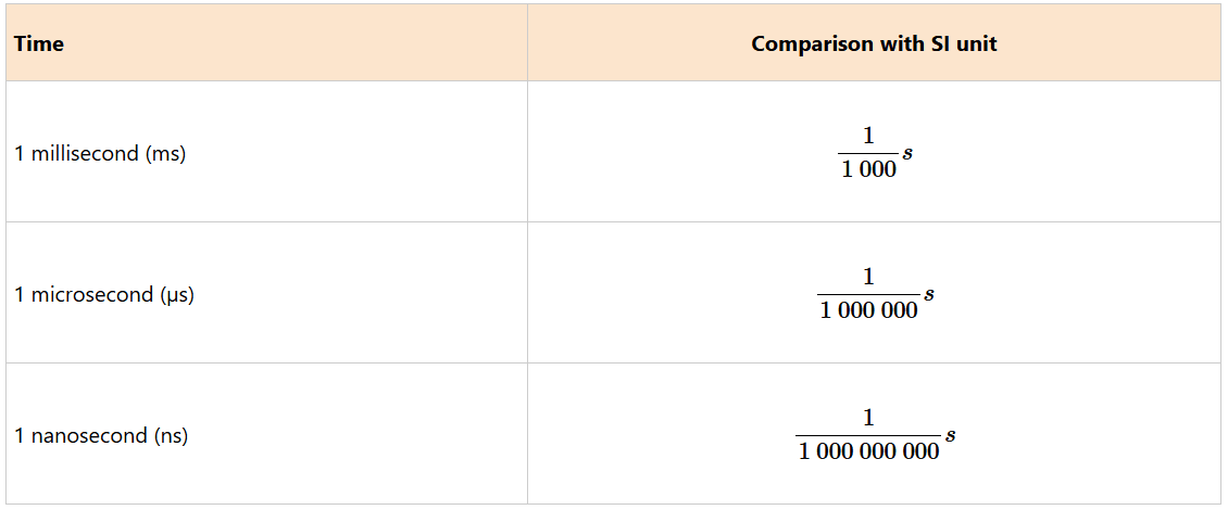
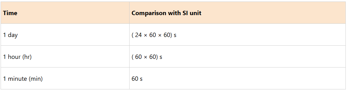
There are smaller units of time that are based on the second. These are the millisecond (ms), the microsecond (μs), and the nanosecond (ns) shown in Table below. Large units of time are minutes, hours, days, weeks, months and years shown in Table 2.6
Small units of time
Large units of time.
Reading time using stopwatch
Time is used to indicate when an event occurs, the order in which several events occurs or the rate at which an event happens. Under normal circumstances, time is usually measured using a clock or a wristwatch shown in Figures (a) and (b), respectively.


For those experiments that require measurement of time in the laboratory, stopwatches are used. At this level, we shall concentrate on measuring time by using a stopwatch.
A stopwatch is a device that is held in the hand and is used to show the time elapsed. Thus, the time interval is obtained from the moment the stopwatch is started to the moment it is stopped.
A stopwatch is used when time must be measured precisely and with a minimum error. Stopwatches are used for timing laboratory experiments or sporting activities such as athletics.
There are two types of stopwatches, namely analogue stopwatch and digital stopwatch as shown in Figure below


An analogue stopwatch has two scales, the minute scale and the second scale. The pointer on each scale enables the time that has elapsed to be read, see Figure 2.20 (a).
A digital stopwatch shown in Figure 2.20 (b) displays the actual time in minutes and seconds. Digital stopwatches are more accurate than analogue stopwatches. A large digital version of a stopwatch is called a stop clock. Stop clocks are designed for distant viewing as in sports stadiums.
How to operate a stopwatch
The timing functions of a stopwatch are controlled by two buttons, one at the top of the watch and the other at the side of the watch. Pressing the top button starts the timer and pressing it again stops the timer.
The elapsed time is then displayed on the screen. The side button usually has two functions, first, to reset the stopwatch to zero and second function to record the split times or lap times. When it is pressed while the stopwatch is running, the elapsed time is displayed, while the watch keeps on recording the time elapsed.
Activity 4
Aim: To determine the period of a simple pendulum.
Materials: String, retort stand, analogue or digital stopwatch and object (200 g)
Procedure
1. With the guidance of your teacher, construct a simple pendulum by tying one end of the string to the retort stand.
2. Tie the 200 g object on the other end of the string.
3. Pull the object slightly to one side and release so that it swings back and forth.
4. Using a stopwatch, measure the time for the pendulum to swing back and forth ten times.
5. Record your observations.
6. Calculate the period (time for one complete oscillation).
7. Record your results.
8. Repeat steps 4-7 four times.
Question
How could you obtain the period (T) of the simple pendulum?

Measurement of mass
Mass is among the fundamental physical quantities of measurement. It is defined as the quantity of matter in an object. It measures the amount of matter in an object. The SI unit of mass is the kilogramme, abbreviated as kg. Other units of mass based on kilogramme are tonne (t), gramme (g) and milligramme (mg). Their equivalences are as given below and in Table 2.7.
1 tonne = 1 000 kg.
1 kilogramme = 1 000 g.
1 gramme = 1 000 mg.
A comparison of the units of mass
Mass should not be confused with weight as is evidenced in day-to-day discussions and conversations. Weight is defined as a measure of the gravitational force acting on an object, or is the measure of how heavy an object is.
Measurement of mass using different instruments
The equipment commonly used to measure mass of an object in the laboratory includes a digital (electronic) balance, shown in Figure 2.21 (a), and a triple beam balance shown in Figure (b).

 (b) Triple beam balance
A triple beam balance
A triple beam balance is used to measure the mass of an object. Its unit of measurement is the gramme. It is called triple beam balance because it contains three beams, each with specified standard mass graduations or markings.
The first beam has 100 g graduations, the second has 10 g graduations and the third beam has 1 g graduations with 0.1 g graduations in between. To measure the mass of an object, the weights which are normally attached to each beam, are moved along the beams.
How to use a triple beam balance
With the pan empty, move the three weights to the left of the beams, so that the balance reads zero, shown in Figure below. The balance pointer should be straight and aligned with the fixed mark at the right of the balance. If the pointer is not straight, use the counter weight to adjust as needed.

1. Once the balance has been adjusted, place the object to be measured on the pan.
2. Move the 100 gram weight to the right along its beam until the indicator just drops below the fixed mark. The mark to the immediate left of this point indicates the number of hundreds of grams. Note down this value which is 0 g for the case of Figure 2.23.
3. Move the 10 gram weight to the right along its beam until the indicator drops below the fixed mark. The mark immediately to the left of this point indicates the number of tens of grams. Note down this value, 20 g for the case of Figure 2.23.
4. Move the 1 gram weight to the right along its beam until the pointer coincides directly with the fixed mark on the right, as shown in Figure 2.23. Note down this value which is 5 g and given to the nearest tenth of a gram.

Example 5
The diagram in Figure 2.24 shows the position of the three weights on the beams of a triple beam balance. Determine the mass of the object.

Solution
Start with 100 g, 10 g, then 1 g. That is, 300 g + 40 g + 3.5 g = 343.5 g.
A digital balance
A digital balance is a very sensitive weighing balance. It can measure masses to an accuracy of one thousandth of a gram (0.001 g). The object whose mass is to be measured is placed on the pan on top of the balance and the mass is read from the digital display.
Task 6
Perform the following tasks:
1. Use a triple beam balance to measure the mass of your physics textbook, exercise book, and your pen.
2. Use a digital balance to measure the mass of the same materials.
3. Compare the two measurements and discuss any differences.
Exercise 3
1. Imagine you want to find out how long a piece of wire is. While doing this, you come across two terms: estimated length and measured length. How do these terms differ?
2. Why do we need to measure things?
3. Outline five (5) different items found in your environment that can be measured in terms of:
(a) Length (b) mass
4. A Form One student was asked to measure time for conducting a science experiment. What items could the student use to accurately measure time?
5. Suppose a teacher asks you to determine the mass of water in a measuring cylinder. How would you do it using a digital balance?
6. Imagine you are using a digital balance to measure the mass of a metallic ball. What is the unit of the reading on the electronic balance?
Derived quantities
Derived quantities are obtained by combining the fundamental quantities through the application of basic arithmetic operations, namely multiplication and/or division.
Their units are called derived units and the same method is used in deriving them. Examples of derived quantities are area, volume, density, velocity, and acceleration.
Their respective derived SI units are m2,m3, kg/m3, m/s and m/s2. Table 2.8 shows some derived quantities and their corresponding SI unit.
Derived physical quantities and their SI units
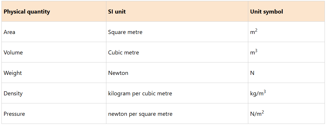
These quantities are calculated using certain formulae or they are determined experimentally. For example, Area (A) of a square = length (l) × length (l) = l × l = l2. The SI unit of area is the square metre, m2. However, areas of other regular shapes are calculated using their respective formulae depending on the shape of the object.
Measurement of volume
Volume is the quantity of space that an object occupies. The SI unit of volume is cubic metre (m3). One cubic metre is the volume of a cube with sides that are one metre long. Other units of volume include:
(a) cubic centimetre (cm3);
(b) millilitre (ml); and
(c) litre (l).
Relative to everyday school laboratory works, a cubic metre is rather a large unit of volume. Therefore, convenience purposes, volumes are measured using the cubic centimetre (cm3). One cubic centimetre is the volume of a cube whose sides are one centimetre long, shown in Figure below.

Litre is another metric unit used to measure the volume of liquids.
1 litre = 1 000 cm3 = 1 000 ml. This implies that 1 cm3 = 1 ml. The volume of water in a 1litre =1/1 000m3 as shown in Figure below.

Techniques for measuring volume
The techniques for measuring volume do vary depending on whether the sample is liquid, solid, or gas. The volumes of liquids are measured using special apparatus; that are graduated in cm3 or ml.
Measurement of the volume of liquid
Several graduated apparatus such as a graduated cylinder, burette, or pipette are usually used to measure the volume of a liquid in the laboratory. Calibrated beakers and flasks can also be used.
In rare cases, syringes are used for measuring the volume of liquids. A burette, a pipette, or a volumetric flask gives accurate measurement of liquid volumes.
Measurement of volume using a measuring cylinder
Measuring cylinders are used to measure the volume of a liquid, ranging from a few millilitres to hundreds of millilitres. They are of different sizes, made of glass or plastic. Measuring cylinders are graduated from the bottom upwards.
They measure the volume of liquids that are poured into them. An example of a measuring cylinder is shown in Figure 2.27.

When reading a measuring cylinder, the cylinder must be placed on a level surface. The curve in the upper surface of the liquid is called the meniscus. The meniscus can curve upward (concave) or downward (convex) depending on the liquid and the material of the cylinder.
The volume of the liquid is read at the top of the meniscus or at the bottom of the meniscus, as illustrated in Figure (a) and (b), respectively. Note that the eye level should be in line with the meniscus of the liquid.

Reading the volume of liquids in a measuring cylinder
For example, Figure 2.29, shows a 1 000 ml measuring cylinder containing blue-coloured water. The volume of water is 700 ml equivalent to 700 cm3.

Task 7
Fill some water in a drinking cup then pour the water into a graduated measuring cylinder. Measure and record the volume of water. What is the reading on the cylinder?
Measurement of volume using a burette
A burette is a vertical cylindrical piece of laboratory glassware with a volumetric graduation on its full length and a precision tap, or stopcock on the bottom, shown in Figure below.
It is used to dispense a required amount of a liquid reagent for which high precision is desired. A burette is graduated from the top downwards and measures the volume of a liquid that runs out from it.

In using a burette the following steps are to be followed:
1. Pour the liquid into the burette and make sure that it does not pass the 0 mark at the top. Note down this volume, say V1.
2. Note down the value of the amount of liquid you require to use, say V and add it to V1 to get V2.
3. Open the tap and let the liquid run until the level of the liquid reaches V2.
4. Subtracting V1 from V2 gives V.
Measurement of volume using a pipette
A pipette is a glass or plastic tube, usually open on both ends. A pipette is shown in Figure 2.31. It is used to transfer a known amount of liquid from one container to another. The liquid is sucked into it until it reaches the level of the mark shown.

Sometimes a flexible rubber bulb is placed at one end of the pipette to aid in sucking the liquid from a container, shown in Figure

Common laboratory pipettes are calibrated with 20 cm3, 25 cm3 or 50 cm3. The 20 cm3 pipette is used to measure 20 ml of liquid while the 25 cm3 and 50 cm3 pipettes are used to measure 25 ml and 50 ml of liquid, respectively. This shows that pipettes are specifically made for transferring small amounts of liquids from one container to another.
Activity 5
Aim: To measure the volume of water using a pipette.
Materials: Pipette, beaker, measuring cylinder and water
Procedure
1. Pour 100 ml of water into a beaker.
2. Transfer 25 ml of water from the beaker to a measuring cylinder using a pipette.
3. Observe the meniscus of the water in the cylinder.
4. Record the volume of water in the measuring cylinder.
Question
How does the original volume of water in the pipette differ with the volume of water in the measuring cylinder? Explain.

The volume of water transferred into the measuring cylinder equals the volume of the pipette. This is because the volume of a liquid does not change, irrespective of the apparatus used.
Measurements of volume of a solid
(a) Determining the volume of regular solid objects
Dimensions of a solid with a regular shape such as a cube, a cylinder or a sphere, can be measured and the appropriate formula is used to calculate its volume.
For example;
Volume (V) of a rectangular block = length (l) × height (h) × width (w).For a cube, l= h = w,
Volume of a cylinder
= π × (radius,r)2 × (height, h) = πr2h
Volume of sphere = 4/3 πr3
Example 6
Calculate the volume of a rectangular block, of sides 15 cm, 8 cm, and 7 cm, shown in Figure 2.33.
Solution

Volume of the block = l × w × h
= 15 cm × 8 cm × 7 cm = 840 cm3
Example 7
Calculate the volume of the cylinder shown in Figure 2.34, given that π = 3.14.

Solution
Given, π = 3.14, r = 5 cm and h = 14 cm
Formula for calculating volume of a cylinder V = πr2h
Substituting in the formula gives,
V = 3.14 × 5 cm × 5 cm × 14 cm
= 1 099 cm3.
(b) Determining the volume of irregular solid objects
Measuring the volume of an irregular shaped solid object is based on the Archimedes’ principle which states that ‘when an object is completely submerged in water, it displaces a volume of water equal to its own volume’. Thus the volume of an irregular object can be measured using:
(i) a measuring cylinder; and
(ii) a eureka can or an overflow can.
Measuring the volume of irregular objects using a measuring cylinder
Suppose you want to measure the volume of a small stone. The following steps are necessary.
1. Fill a measuring cylinder with about 300 mL of water as illustrated in Figure 2.35 (a).
2. Carefully measure the initial volume of water V1.
3. Gently lower the stone into the water as shown in Figure 2.35 (b).
4. Read the final volume of water V2.
5. The difference between the final and the initial volume gives the volume of the stone.
Volume of the stone Vs = final volume (V2) − initial volume (V1)
Vs = V2 – V1.

In the illustration,
Vs = 600 ml − 300 ml = 300 ml.
Example 8
When an irregular solid object was immersed in 65 cm3 of water, the water level rose to 81 cm3. What was the volume of the irregular solid object?
Solution
Initial volume of water V1 = 65 cm3
Final volume of water V2 = 81 cm3
The volume of solid, Vs = V2 − V1
Vs = 81cm3 − 65cm3 = 16cm3
Therefore, the volume of the irregular solid is 16 cm3.
Measuring the volume of an irregular object using a eureka can
If the object is too large to fit into the measuring cylinder, an alternative method is to use an overflow can commonly known as the eureka can shown in Figure 2.36. This is a large can with an overflow spout near the top. In practice, the following steps are involved when using an overflow can to measure the volume of an irregular object.
1. Fill the eureka can with water up to the level of the spout, as illustrated in Figure below

2. Tie the irregular object with a string.
3. Gently lower the object into the water using the string.
4. The object will displace some water which will be collected in the beaker, shown in Figure below

5. Transfer the displaced water into a measuring cylinder, shown in Figure 2.38.
6. Measure the volume of the displaced water. The volume of the displaced water is equal to the volume of the object under study,

Note: The volume of solid objects with irregular shape can be determined by using immersion methods.
Activity 6
Aim: To measure volume of an irregular object using a eureka can.
Materials: eureka can, stone, water, beaker, measuring cylinder and string

Procedure
1. Set up the apparatus as in Figure 2.39.
2. Tie the stone with a string and gently lower it into the water contained in the eureka can.
3. Collect the overflowing water in the beaker below the spout.
4. Measure and record the volume of the displaced water using a measuring cylinder.
Questions
(a) Why must the stone be tied and gently lowered into the water?
(b) Why is the water in the eureka can displaced when the stone is immersed?

The stone is tied before lowering so that it can be gently lowered to prevent water from splashing. If water splashes wrong results may be recorded as the remaining water level would be lower than the spout level. It would also interfere with the volume to be measured.
The water in the eureka can is displaced so as to give room for the stone. The stone occupies a volume which is equal to the volume of water displaced.
If the solid has an irregular shape such as a stone, it is submerged in a measuring cylinder containing water and the volume of water displaced is taken as the volume of the solid. Note that, the method of immersion can also be used to measure the volume of regular object.
Measurement of volumes of gases
A gas always fills any container into which it is placed. Therefore, the volume of a gas can be determined by measuring the volume of the container that holds the gas. The volume of the container can be determined from its dimensions or by filling it with water and then pouring the water into a measuring cylinder.
Exercise 4
1. Calculate the volume of a cube of sides 2 cm.
2. The volume of a brick is given as 60 cm3. Given that its length and width are 6 cm and 4 cm respectively, calculate its height.
3. A cylindrical container has a diametre of 10 cm and a height of 12 cm. Calculate its volume, given that π = 3.14.
4. A beaker contains 100 cm3 of liquid. A 25 cm3 pipette is used twice to transfer the liquid to another beaker. What is the volume of the liquid left in the original beaker?
5. The initial volume in a burette was read as 80 cm3. Suppose X cm3 of the liquid was run out and the final volume was read as 57 cm3. Calculate the value of X.
6. What is the volume of an irregular solid immersed in 50 cm3 of water contained in a beaker if it raises the water level to 57 cm3.
Sources of errors
While taking any measurement, there may be some error in the reading. An error is defined as a deviation from the actual reading. However, there is a more precise definition.
An error is a measure of estimated difference between the measured value and the actual value of a physical quantity that is being measured or observed.
Errors usually arise due to several reasons:
1. An instrument fault during manufacture – If a measuring instrument is not manufactured as per specification, then the accuracy is lowered.
2. Damage during use – Bad handling of instruments can lead to incorrect results. Each apparatus should be used properly and for the right purpose.
3. Poor storage – Apparatus should be well stored away from factors that affect their accuracy like dust and heat.
4. Human factors – Errors can arise when an experimenter does not take readings from an instrument properly.
There are three common errors caused by improper reading of an instrument these are:
(i) Parallax error;
(ii) Zero error; and
(iii) Instrumental error
Parallax error
Parallax error occurs when an observer takes measurement from wrong positions. Consider Figure below

Positions 1 and 3 will give higher and lower readings than position 2. A reading taken at position 2 will be correct because the observer has positioned his/ her eyes directly above the mark to be read. Thus, to minimize parallax error, the observers must position their eyes directly above the mark to be read.
Zero error
For a measurement to be considered accurate, the initial reading of a pointer should be at a zero mark.


When a measurement is taken using an instrument with the pointer below or above the zero mark shown in Figure (a) and (b), zero errors occur. To minimise zero error, the instrument should be adjusted to read zero, shown in Figure. A pointer can be adjusted to read zero.

For example, in a vernier calliper, zero error arises when the zero mark on the main and vernier scales do not coincide with each other when the jaws are closed. A micrometre screw gauge may also have zero error if the zero mark on the spindle and sleeve do not coincide after closing the gap between the spindle and the anvil.
Instrumental error
An instrumental error is caused by the instrument itself. The error occurs because of defects in the instrument used in taking a measurement. These defects can be from the manufacturer or poor handling of the instrument. Sometimes errors of this type may occur when the instrument used for measuring is overheated. Also, insensitivity of the instrument can result in this error. To minimise these errors, avoid overheating instruments, maintain them regularly and store all instruments in a safe place that is free from dust. Proper handling of instruments is also recommended.
Project
Aim: Making a ruler using locally available materials
Description: In this project, you will have the opportunity to design your own ruler using materials that are available in your environment. By conducting this project, you will develop measurement skills and improve your problem solving abilities. Additionally, this project serves as a foundation for conducting various explorations in physics and other scientific disciplines.
Resources: cardboard, wood, or plastic, measuring scale, marker or pen, scissors or craft knife, sandpaper, coloured markers or stickers to make the ruler visually appealing, and any other useful resources
Procedure:
1. Plan the design of the ruler considering the length and width you want to achieve.
2. Carefully cut the base material (cardboard, wood, or plastic) to the desired length and shape of the ruler using scissors or a craft knife.
3. Smoothen the edges and surface of the ruler using sandpaper to ensure there are no rough edges that could affect the accuracy of measurements.
4. Using a standard measuring scale or an existing ruler, scale your ruler with proper graduations.
5. Test the ruler by measuring various objects found in your environment to check its precision and correctness. Use a standard ruler as a reference.
6. Share your product with others and discuss the process undertaken to design it.
7. Establish the measurement error of your designed ruler.
Reflection
How will the knowledge and skills gained in this project shape your daily life?
Chapter summary
1. Initially, approximations were used as a form of measurement. Advancement in science has made it possible to have appropriate instruments for each type of measurement.
2. Every measurement has the number part and the unit part. This complete measurement is called the measurement of a physical quantity.
3. Fundamental quantities are the physical quantities which cannot be obtained from any other quantities. These quantities include length, mass, time, temperature, amount of substance, electric current and luminous intensity.
4. Fundamental physical quantities are measured using base units which are metre (m), kilogramme (kg), second (s), kelvin (K), mole (mol), Ampere (A) and Candella (cd).
5. The beam balance and digital balances are used to measure mass, while rulers, vernier callipers, micrometre screw gauges and tapes are used to measure length. On the other hand, time is measured using a stopwatch or a clock.
6. Derived quantities are obtained by dividing or multiplying two or more fundamental quantities. These quantities include weight, acceleration, velocity, volume and area. Their SI units are the newton, metre per second square, metre per second, cubic metre, and square metre, respectively.
7. There are three types of errors that emerge during measurements, namely:
(a) parallax error;
(b) zero error; and
(c) instrumental error.
Revision Exercise
Section A
1. Choose the most correct answer
(i) To measure the length using a metre rule, wrong position of the eye leads to:
(a) parallax error.
(b) eye error.
(c) zero error.
(d) metre error.
(ii) Which of the following instruments is most suitable for measuring the internal diametre of 100 ml beaker?
(a) Metre rule.
(b) Vernier calliper.
(c) Measuring tape.
(d) External calliper.
(iii) The mass of an object is reduced if its
(a) state is changed.
(b) amount of matter is reduced.
(c) surface is reduced.
(d) volume is reduced.
(iv) A cuboid with length 3 cm, width 4 cm and height 10 cm is made from wood. The actual volume of the cuboid is
(a) 120 cm3.
(b) 240 ml.
(c) 120 m3.
(d) 240 cm3.
(v) What is the zero-error shown in the Figure below?

(a) 0.3 mm
(b) 0.7 mm
(c) -0.3 mm
(d) -0.7 mm
Section B
2. (a) From the listed objects, classify them in terms of regular or irregular shape. Objects: Cube, orange, stone, banana, water pipe, a house, cuboid, chalkboard.
(b) The internal and external radius of a hollow silver sphere are 7 cm and 14 cm, respectively. Find its volume.
(c) A student measures the length of a table to be 1.5 m with a ruler that has a precision of 0.1 cm. What is the uncertainty in the measurement?
3. In a vernier calliper, there are 10 divisions on the vernier scale and 1 cm on main scale is divided in 10 parts. While measuring a length, the zero of the vernier scale lies just ahead of 1.8 cm mark and 4th division of vernier scale coincides with a main scale division. Find the value of the length.
4. (a) Differentiate between the mass and the volume of a substance.
(b) Figure 2.44 shows a measuring cylinder containing water before and after a stone is immersed. What is the volume of the stone?

5. The Figure below shows a metre rule being used to measure the length of a textbook.

(a) What is the approximate length of the book?
(b) Explain why it is advised to start at the mark beyond 0 cm when taking a measurement using a metre rule.
6. A physics student obtained the following results for the diametre of the same wire from an experiment: 0.35 mm, 0.36 mm and 0.34 mm. Calculate the diametre of the wire.
7. A rectangular block measures height 1.00 cm, width 2.50 cm, and length 4.00 cm.
(a) What instrument was used to measure the sides of the rectangular block?
(b) Calculate the volume of the rectangular block.
8. A student repeatedly measures the mass of an object as 49 grams, while the actual mass is 52 grams. What conclusions can be drawn about the accuracy of the student’s measurements?
9. When a car was first seen, the stopwatch start button was pressed. When the car passed the observer, the stopwatch showed 01: 02. How long did the car take to reach the observer?
10. An athlete runs round a track three times. Her friend uses a stopwatch to record the time elapsed. At the start of the ride, the stopwatch recorded 6.00 s, after one round the stopwatch recorded 180.00 s and at the end of third round the reading from the stopwatch was 600.00 s. What is the average time for one round of the track?